To paraphrase Vane Jones, "Knowledge is of little value until shared with others."

Wednesday, May 15, 2013

The AE&C Florence part 2


When the model was received from Jim Osborn, a separate interior floor with the partitions for the lavatory and buffet was included with the model. Unfortunately a photo of the styrene model was not taken. 


To give you an idea as to what the body shell might look like, this is a CA&E 700 series car body. The model is bare without handrails and other details. The roof has been primered plus the model has been mounted on trucks by me..


This body shell came with the steps. Most of the time the modeler has to add the steps  The center line of the floor is marked on the underside. Depending upon the model the truck centers may be marked. If the model has a rounded  anticlimber, the center of the radius is marked.

ELECTRICAL
The best place to start is with an electrical diagram of the model. These are the given constraints: 1) the model is a trailer although the prototype is a powered car, 2) there are trolley poles which can be used to pick-up electrical current although this model will receive track voltage from the lead car, 3) a Dallee adjustable power supply will be used to control the 1.5 v bulbs, and 4) besides interior lighting the model will have a pair of rear-end marker lamps plus the standard MET rear-end red lamp.

Some of the constraints require explanation. The model of the Florence needs a jack for the 12-18 v pigtail from the lead car to plug into.  As an aside, any CA&E models which are to be run together need to have a method to buss the trolley current between them. Only the trolley pole on the lead car is to be up when multiple cars are run in a train.

Although the Dallee adjustable units are expensive 2 units are being install - 1 in 314 car and 1 in the Florence.  One Dallee unit should be able to handle all the bulbs in both cars. The Florence may not always be trained with the 314. It's better if the Florence can be run with other  models and still be able to have constant voltage lighting. Also, the Florence can be on a siding by itself and "plugged" into track voltage with the lights on for display purposes.

The rear-end markers will be PSC brass castings. The standard MET required rear-end red lamp will be scratch-built.

This is the electrical diagram for the Florence. Please excuse my rough drawing.

TRUCKS
The trucks are PSC Baldwin 7830 with NWSL wheels and Q-Car Co. CA&E 3rd rail beams were glued on using ACC.


DETAILS
Now is the time to add details to the model. The MET required rear-end red lamp was a special lamp to be displayed on the rear on trains on the Garfield Park Division of the MET from sun set to sun rise. Since the AE&C and later the CA&E when operating on the "L" operated by the same rules as the MET. the AE&C had to have the same type of red lamp.

Today these red lamps are extremely rare. To get an idea how one of these lamp looked like take a look at the photo of a MET rear-end red lamp on page 79 in The Shore Line Interurban Historical Society "Dispatch Number 1, Cooperation Moves the Public". The red lens is a big as the width of the lamp housing. The lens is also bigger than the lens on a marker lamp.

This is another photo of the same lamp. Bruce Moffat has had the lamp mounted for furniture top use. Notice the "D" rings on the bottom of the lamp base. These make the lamp a CRT rear-end red lamp. The CRT had this type of lamp as well as the CA&E. If you read "Cooperation Moves the Public" you will under stand the reason for the lamp.


The CA&E lamps were able to mount on the rear door of the train in the same location and style as the headlight on the front of the train. The CRT didn't always have a flat panel door on to which the rear-end red lamp could be installed. Instead the CRT cars had chains. To secure the lamp and to prevent the lamp from swinging to and fro, the top chain was placed through the handle of the lamp while springs from the "D" rings to the lowers chain hooks were used to secure the lamp in place.

To make the housing a piece of square styrene tubing was used. It was cut longer than required. A hole was made in one side of the square tubing. Then a piece of short round tubing of the same size was glued over the hole. The round tubing was filed down to about the size of the red lens holder on the lamp. A twist drill was manually twisted into the round tubing to make it look more like the size and shape of the  red lens holder.

Next the square tube was filed short on the bottom and top. Top and bottom styrene pieces were attached. Finally to make the chimney part of the lamp the top of a brass marker light was used.

The light bulb and red lens will not be added until the lamp is painted and attached to the model.

The balance of the exterior details were prepared and installed on the model.

There is always more to come!

Cheers,
Ed

Monday, May 13, 2013

The 2013 East Penn Traction Meet

This year's East Penn Traction Meet was a success. There were a large number of vendors as well as attendees. Some may complain of the show next door to the EPTC Meet or of low attendance.

The Meet was held in a large building called the Greater Philadelphia Expo Center. The "locals" say it's a misnomer to call it that. Since the location is so near to Valley Forge maybe it should be the Valley Forge Expo Center. The building reminds me of a building supply/lumber yard business which had gone out of business.

The EPTC has no control over to whom the other parts of the building are rented on a weekend. The weekend of the Traction Meet we counted at least 4 other events booked into the same building. The building is huge!

Since the area the traction Meet was in proportion to how large the total space of the building is, on Friday vendors were setting up plus individuals like us who were from out of town and nothing else to do were at the Meet. Far more attendees were at the Meet on Saturday. 

If you want to get business done with a particular vendor Friday is the day to do it. I had to talk with Jim Osborn about a number of items so Friday was a "God send". Jim and I were able to catch-up on old personal stuff plus some new business.

The secret to having a good experience is finding out how to get to the Expo Center from your hotel/motel. We always turn southwest at the "fireless cooker" on the corner of Egypt Rd. and Station Ave.; Oaks, PA. There's also railroad station on the corner. I have no idea what the area was a one time but you'll notice railway track and at least 4 very small locomotives on the track to the west of Station Ave as you drive to the Expo.

Since the Expo building is very large drive around it at least once to find the correct entrance for the EPTC Meet along with parking. Many of us have commented to the EPTC about the lack of appropriate signage once the turn at Egypt Rd. and Station Ave. is made. For at least the last 2 years the area around Egypt and Station has been under construction!

Back to the Meet, EPTC is both O scale and HO scale with appropriate portable layouts made up of modules. Since I'm interested in O scale that is what I'll write about. EPTC had both the regular, older form of DC control layout and a new DCC layout.

This was the central control module for the regular control layout. From it cars/trains can be sent into one of 3 different routes. Cars/trains can be stored in the yard behind and next to the station.

The street scene is one of the 3 legs into which cars can be routed.

This is a different routing into which cars can be placed. If you can count the number modules and multiply by 2 feet (Modules can vary in length. The 2 feet was arbitrarily picked by me.) you can get an idea as to how long the leg is.


Multiple cars were running without problems. A form of block control is used to prevent accidents.

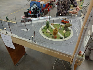
On the DCC control modular layout this was the central control module. There were either straight through, around the curve, or turn back, around the monument, running.


These are 2 of the more unusual modules.


One of the more creative displays by Curt Seeliger of a vendor was -

Finally I'm an EPTC member and I live in the Chicago area about 700-800 miles from the East Penn area. You should also be a member. You might say I don't live anywhere near East Penn. The membership dues are not that big. Even if you may not like their newsletter or can't make local meetings, the traction community needs to keep the EPTC alive. Check out their website http://www.eastpenn.org/ . Where else can you find as much up-to-date information about traction? Where else can you find information about modules and module standards which work?  What about keeping the EPTC operating if only for them to put on the bi-annual EPTC Meet?

Here is an application. Fill it out today and mail it! Tell them Ed sent you!
 

Cheers,
Ed

Wednesday, May 1, 2013

Joel Lovitch of MTS Imports Retires

In an email to the "Interurbans Yahoo Group" Joel Lovitch announced his retirement. 
 
The text of his message stated: 
 
"WE ARE RETIRING!.
 
"AFTER 40 YEARS OF SERVING THE MODEL TRACTION HOBBY, IT IS TIME TO RETIRE AND GET BACK OT THE HOBBY WHICH WE LOVE SO MUCH.
 
"WHILE INVOLVED IN THE MODEL TRACTION BUSINESS WE DID NOT HAVE TIME TO DO ANYTHING FOR OURSELVES. IT IS NOW TIME TO GET BACK TO MODELING.
 
"WE WILL BE EXHIBITING AT THE EAST PENN TROLLEY MEET IN OAKS, PA ON MAY 3RD AND 4TH.
 
"WE WILL HAVE DISCOUNT PRICING ON ALL MTS BRASS MODELS THAT REMAIN IN STOCK (THERE WILL BE A FEW EXCEPTIONS FOR OLDER MODELS THAT ARE NO LONGER AVAILABLE).
 
"WE WILL BE LOCATED NEXT TO THE CUSTOM TRAXX/BOWSER TABLES.
 
"STOP BY AND SAY HELLO AND SEE WHAT WE HAVE TO OFFER.
 
"JOEL LOVITCH
MTS IMPORTS, INC."
 
A giant THANK YOU goes to Joel for his products over the 40 years. They were fantastic and set a standard for the attention to detail  each model had. 

Joel, the very best to you!

See you, all of you, at the East Penn Trolley Meet.

Cheers,
Ed